We started the day off with an kinematics exercise that had us find the distance an electron will travel between a set of charged plates. This exercise led to a live demonstration of an electron beam whose position was being aimed with external voltages on a series of plates that the beam traveled through. The purpose of this demonstration was to show the class the inner mechanics of the oscilloscopes display screen.

The next exercise of the day consisted of connecting a function generator to a speaker and having the generator output frequencies in the audible range. A function generator is a device that is capable of outputting an AC voltage at specific frequencies and wave shape. We learned that the frequency of the signal controls the pitch of the sound from the speaker, and the magnitude of the output voltage controlled the loudness.

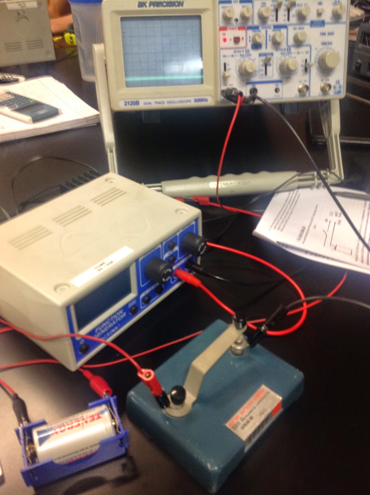
The next exercise was measuring the voltage of a battery with the oscilloscope using a tap key in series with the battery. With the oscilloscope set to DC coupling, and appropriate values for volts/div and time/div set, we were able to measure the voltage of the battery at around 1.2 volts.

The next exercise consisted of measuring the voltage of two different power supplies and then using those measurements to compare the quality of each supply. We started off by measuring the voltage of a small table top power supply and found that there was a very fine amount of AC voltage that was delivered in the DC power supply's voltage. The next power supply measured was the output of a standard wall adapter. It was found that the voltage of the adapter varied greatly over time. It was concluded that the quality of the wall adapter was not very good.

After testing the power supplies, we moved on to an exercise involving Lissajous Figures. Pressing in the x-y button on the oscilloscope caused the display to enter a mode where channel 1 would drive the x-axis and channel 2 would drive the y-axis. Connecting function generators to both channels and setting both generators to varying frequencies cause the display to show various figures and shapes referred to as Lissajous Figures.


The final exercise of the day dealt with taking measurements from a box made up of unknown circuitry. Measurements showed that the box's circuits generated a variety of square wave functions.

The square waves generated by the box differed in duty cycle.

No comments:
Post a Comment