Friday, May 23, 2014


Tuesday, May 13, 2014
Mon. Week 12, May 12: Applications of Magnetic Force
On this day we set out to learn how the properties of magnatism that we learned from the previous class could be used in practical situations. One of these applications is the motor, a device that converts electrical energy into rotational motion. The motor is the heart of all automation and motion in electric devices.
The first exercise we performed was energizing a small motor and seeing how changing the magnetic field through it affects its motion.

After developing an intuitive understanding of how the orientation of the magnetic field affects the torque on the coil windings, we then set out to make our own motors from just wire with a current passing through it and a magnet.

After taking some time to make various adjustments, the simple motor proved to be operational and the exercise was a success.

The first exercise we performed was energizing a small motor and seeing how changing the magnetic field through it affects its motion.
After developing an intuitive understanding of how the orientation of the magnetic field affects the torque on the coil windings, we then set out to make our own motors from just wire with a current passing through it and a magnet.
After taking some time to make various adjustments, the simple motor proved to be operational and the exercise was a success.
Monday, May 12, 2014
Wed. Week 11, May 7: Intro to Magnetism
Magnetism was today's topic of conversation. Permanent magnets are made up of elements that contain a large number of electrons alone in their orbitals. The unpaired electrons create a field that is similar to the electric field created by a charge. This field is known as the magnetic field and has many important properties that relate to electric current and force.
The first exercise of the day was drawing up our predictions of the magnetic field for a bar magnet. The field lines extend from the north to south pole of the magnet and the magnetic flux through any closed surface is always zero.

We eventually came to the topic of how magnetic fields interact with moving charges. Since a moving charge exerts a magnetic field, it will interact with any external magnetic field, which will in turn apply a force on that moving charge. The resulting force is referred to as magnetic force and acts in the direction that is perpendicular to the directions of the charge's velocity and the external magnetic field. With this in mind, we deduced that a charge traveling at constant velocity with travel in a circular path within a uniform magnetic field.

After deriving several equations for magnetic force, we performed an experiment to find the value of the magnetic field for a bar of specific length, with a specific current running through it, moving at a specific acceleration.

The first exercise of the day was drawing up our predictions of the magnetic field for a bar magnet. The field lines extend from the north to south pole of the magnet and the magnetic flux through any closed surface is always zero.
We eventually came to the topic of how magnetic fields interact with moving charges. Since a moving charge exerts a magnetic field, it will interact with any external magnetic field, which will in turn apply a force on that moving charge. The resulting force is referred to as magnetic force and acts in the direction that is perpendicular to the directions of the charge's velocity and the external magnetic field. With this in mind, we deduced that a charge traveling at constant velocity with travel in a circular path within a uniform magnetic field.
After deriving several equations for magnetic force, we performed an experiment to find the value of the magnetic field for a bar of specific length, with a specific current running through it, moving at a specific acceleration.
Mon. Week 11, May 5: Intro to Electronics
The subject of this day's lecture and lab was that of electronics, more specifically, the diode and the transistor. The diode is a component made up of two layers of a semiconductor material that has been doped with elements that give one of the layers a significant amount of free electrons and the other layer a significant amount of electron holes. When these two layers are brought into contact, the free electrons and holes combine and create what is know as the depletion region. If voltage is applied in one direction, the region shrinks and the diode acts as a conductor, but when voltage is applied in the reverse direction, the region grows and becomes and insulator, making the diode a one-way street for current. The transistor is essentially two diodes place back to back and has the ability to act as a switch.
For the first exercise of the day, we were tasked with created a circuit that displayed the voltage amplifying abilities of the transistor. When a signal was applied to the input of the circuit, that signal would be significantly larger in magnitude at the output.

With the oscilloscope connected to the input and output of our circuit, we were able to verify that the signal had indeed be amplified.

We also noticed that the output signal would get cutoff if we applied too much voltage on the input signal. We learned that this was due to the transistor being driven into saturation from the large amounts of voltage being applied to the base.

The transistor is a three lead component. Each lead corresponds to parts of the transistor known as the emitter, collector and base.

For the final portion of the day, we were introduced to the op-amp and the concept of integrated circuitry. An integrated circuit is an entire circuit that is boxed as an individual component. The op-amp is an integrated circuit that can act as a voltage comparator. By using the properties of feedback, the op-amp can be used as a signal amplifier much like the circuit that was previously built.

The amplifier circuit was built and tested with the output from a device that is capable of outputting sound to a speaker jack such as a phone. The low voltage signal was passed through the circuit and sent to a speaker, where the low voltage signal had gained enough voltage to be loud enough for everyone the hear.

For the first exercise of the day, we were tasked with created a circuit that displayed the voltage amplifying abilities of the transistor. When a signal was applied to the input of the circuit, that signal would be significantly larger in magnitude at the output.
With the oscilloscope connected to the input and output of our circuit, we were able to verify that the signal had indeed be amplified.
We also noticed that the output signal would get cutoff if we applied too much voltage on the input signal. We learned that this was due to the transistor being driven into saturation from the large amounts of voltage being applied to the base.
For the final portion of the day, we were introduced to the op-amp and the concept of integrated circuitry. An integrated circuit is an entire circuit that is boxed as an individual component. The op-amp is an integrated circuit that can act as a voltage comparator. By using the properties of feedback, the op-amp can be used as a signal amplifier much like the circuit that was previously built.
The amplifier circuit was built and tested with the output from a device that is capable of outputting sound to a speaker jack such as a phone. The low voltage signal was passed through the circuit and sent to a speaker, where the low voltage signal had gained enough voltage to be loud enough for everyone the hear.
Friday, May 2, 2014
Wed. Week 10, April 30: The Oscilloscope
Today we were introduced to the oscilloscope. An oscilloscope is a measurement device used to show how a voltage through a particular circuit changes with time. Oscilloscopes a particularly useful in trouble shooting AC circuits.
We started the day off with an kinematics exercise that had us find the distance an electron will travel between a set of charged plates. This exercise led to a live demonstration of an electron beam whose position was being aimed with external voltages on a series of plates that the beam traveled through. The purpose of this demonstration was to show the class the inner mechanics of the oscilloscopes display screen.

The next exercise of the day consisted of connecting a function generator to a speaker and having the generator output frequencies in the audible range. A function generator is a device that is capable of outputting an AC voltage at specific frequencies and wave shape. We learned that the frequency of the signal controls the pitch of the sound from the speaker, and the magnitude of the output voltage controlled the loudness.

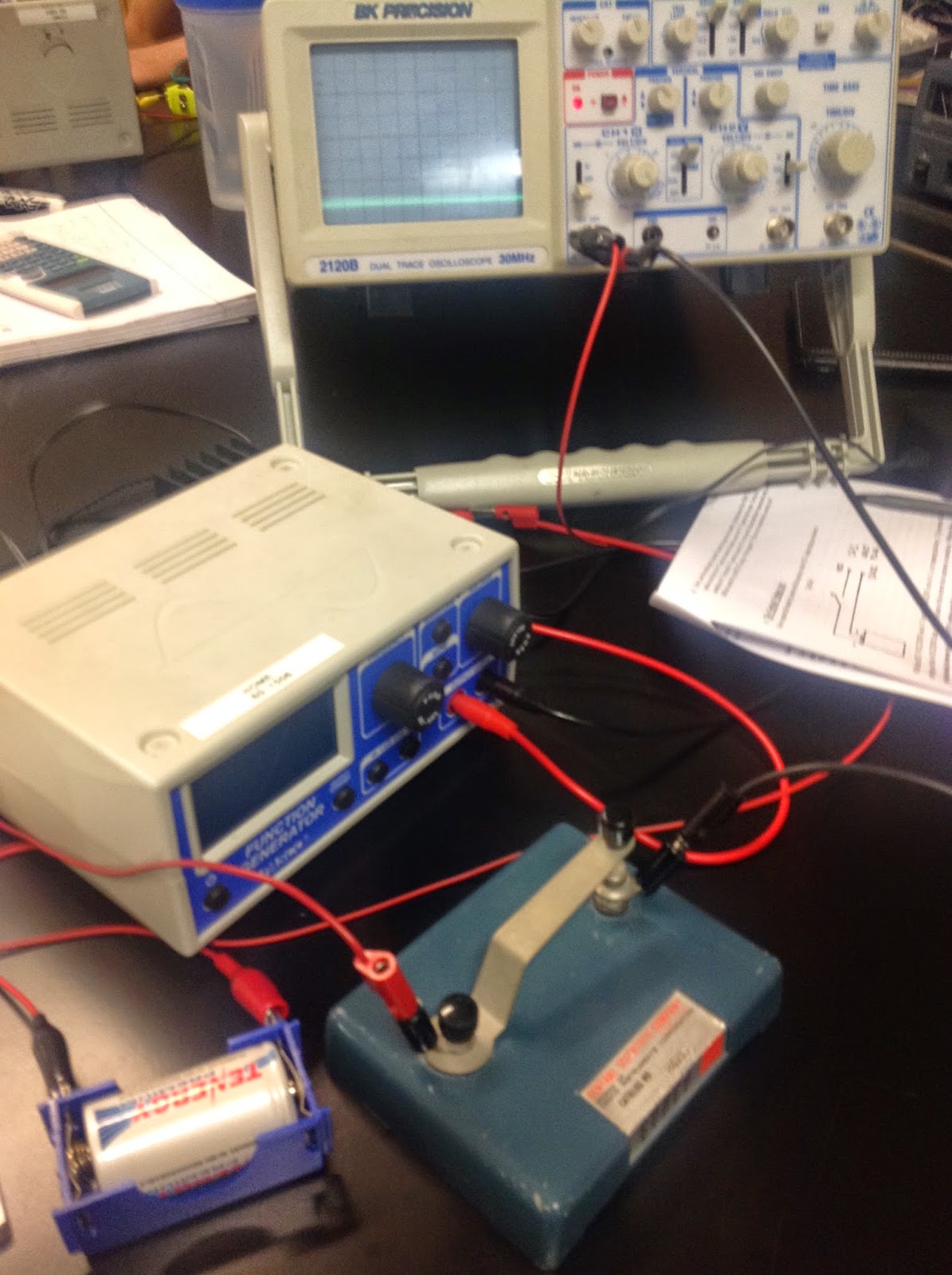
The next exercise was measuring the voltage of a battery with the oscilloscope using a tap key in series with the battery. With the oscilloscope set to DC coupling, and appropriate values for volts/div and time/div set, we were able to measure the voltage of the battery at around 1.2 volts.

The next exercise consisted of measuring the voltage of two different power supplies and then using those measurements to compare the quality of each supply. We started off by measuring the voltage of a small table top power supply and found that there was a very fine amount of AC voltage that was delivered in the DC power supply's voltage. The next power supply measured was the output of a standard wall adapter. It was found that the voltage of the adapter varied greatly over time. It was concluded that the quality of the wall adapter was not very good.

After testing the power supplies, we moved on to an exercise involving Lissajous Figures. Pressing in the x-y button on the oscilloscope caused the display to enter a mode where channel 1 would drive the x-axis and channel 2 would drive the y-axis. Connecting function generators to both channels and setting both generators to varying frequencies cause the display to show various figures and shapes referred to as Lissajous Figures.


The final exercise of the day dealt with taking measurements from a box made up of unknown circuitry. Measurements showed that the box's circuits generated a variety of square wave functions.

The square waves generated by the box differed in duty cycle.

We started the day off with an kinematics exercise that had us find the distance an electron will travel between a set of charged plates. This exercise led to a live demonstration of an electron beam whose position was being aimed with external voltages on a series of plates that the beam traveled through. The purpose of this demonstration was to show the class the inner mechanics of the oscilloscopes display screen.
The next exercise of the day consisted of connecting a function generator to a speaker and having the generator output frequencies in the audible range. A function generator is a device that is capable of outputting an AC voltage at specific frequencies and wave shape. We learned that the frequency of the signal controls the pitch of the sound from the speaker, and the magnitude of the output voltage controlled the loudness.
The next exercise was measuring the voltage of a battery with the oscilloscope using a tap key in series with the battery. With the oscilloscope set to DC coupling, and appropriate values for volts/div and time/div set, we were able to measure the voltage of the battery at around 1.2 volts.
The next exercise consisted of measuring the voltage of two different power supplies and then using those measurements to compare the quality of each supply. We started off by measuring the voltage of a small table top power supply and found that there was a very fine amount of AC voltage that was delivered in the DC power supply's voltage. The next power supply measured was the output of a standard wall adapter. It was found that the voltage of the adapter varied greatly over time. It was concluded that the quality of the wall adapter was not very good.
After testing the power supplies, we moved on to an exercise involving Lissajous Figures. Pressing in the x-y button on the oscilloscope caused the display to enter a mode where channel 1 would drive the x-axis and channel 2 would drive the y-axis. Connecting function generators to both channels and setting both generators to varying frequencies cause the display to show various figures and shapes referred to as Lissajous Figures.
The final exercise of the day dealt with taking measurements from a box made up of unknown circuitry. Measurements showed that the box's circuits generated a variety of square wave functions.
The square waves generated by the box differed in duty cycle.
Subscribe to:
Posts (Atom)